Wire-laid HF RFID antennas offer a number of advantages over printed, etched or galvanized antennas. The shape of the antenna is only limited by the dimensions of the carrier material and the position of the microchip(s) and is otherwise freely selectable. These freely programmed shapes can be quickly transferred to an automatic machine via operating software, so that there is no waiting time for the creation of a negative or similar. The process is ecologically harmless, as no additional chemicals such as solvents are required and it guarantees a long service life and high product quality.
The process
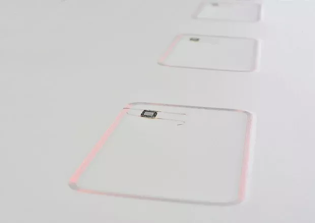
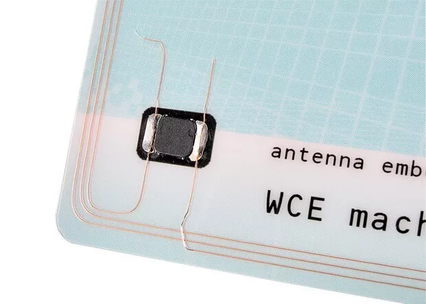
Wire-laid antennas are mainly used in the production of inlays for contactless chip cards. The chip is first placed on a substrate. The coil is manufactured directly by laying a wire on the substrate and connecting the coil ends to the chip's connection surfaces.
Coils can also be attached directly to the substrate using the etching process. However, this process is considerably more complex and coils can only be produced with a relatively low copper density, which means that only a low transmission power is possible.
Attaching wound coils to a substrate requires complex handling and subsequent "bonding" of the coil to the substrate. This means that further work steps are necessary to create a transponder, which makes this process complex and cost-intensive.
With the laying technique, the coil is produced directly on the substrate, as already mentioned. This makes a previously manufactured winding coil superfluous. The production of the coil and the connection of coil wire ends to the connection surfaces of the chip merge into one another and can be carried out in a single work step. This means that one end of the coil can first be connected to a connection surface of the chip, whereupon the coil is formed on the substrate and finally the other end of the coil is connected to a second connection surface of the chip.
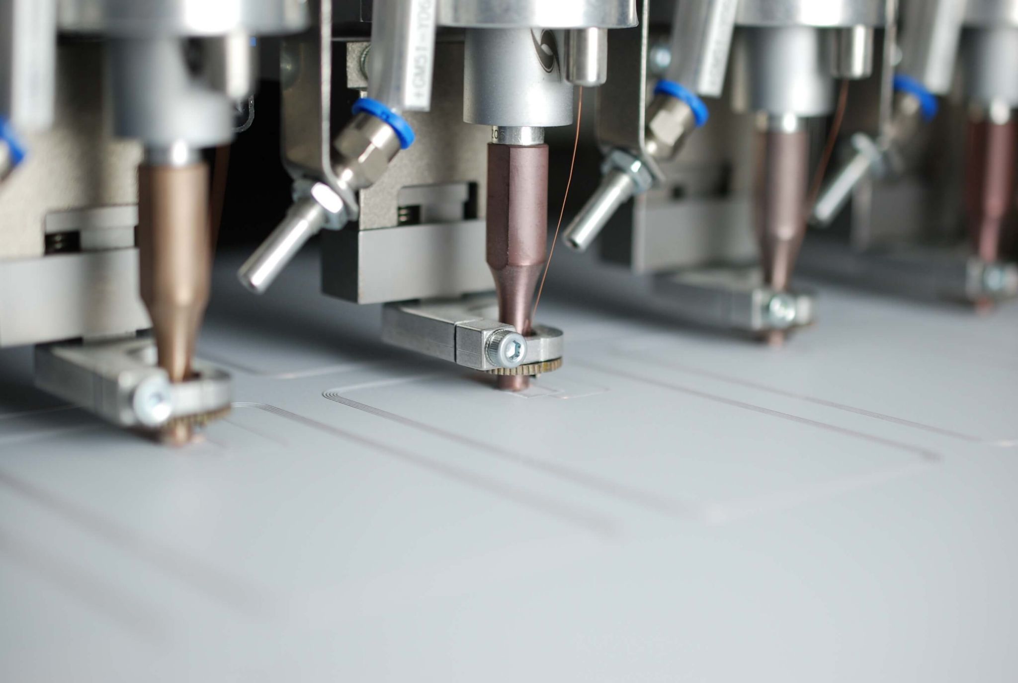
The wire is inserted into the substrate using ultrasound. A so-called& sonotrode, consisting of an ultrasonic transducer and a wire feedthrough in the head, heats the wire at certain points to such an extent that it melts into the substrate material. If the sonotrode is moved at the same time, the antenna coil can be drawn into the substrate.
Laying wire with the help of adhesive foils
To ensure that the wire forms a durable bond with the carrier material, a thermoplastic material must be used into which the wire can melt. A wire coated with baking varnish can also be used. The baking varnish melts under the influence of heat and bonds with the carrier material. If the carrier material is coated with a thermoplastic adhesive film as an adhesion promoter, materials can also be used that cannot be melted thermally and do not form a bond with a known baking varnish. This process enables the use of a wide variety of base materials and the installation of a wide variety of wire designs. Adhesive films can also be used to bond materials with different properties.
The adhesive film (e.g. polyurethane film) is first bonded to the base material by thermal lamination . The coil can then be drawn using ultrasound, whereby the adhesive film melts locally and forms a bond with the wire.
Ultrasound
Ultrasound refers to sound waves beyond the range audible to humans (frequencies greater than 20 kHz). In practice, vibrations are generated electrically. A piezo crystal acts as a transducer and generates mechanical vibrations of the same frequency from electrical vibrations.
The resulting sound wave oscillates in the direction of propagation, also known as a longitudinal wave. The wave is reflected at the end surface of the sonotrode, creating a standing wave. The vibrations transmitted to the substrate lead to molecular and interfacial friction, which in turn generates heat. The plastic softens and the wire is placed in the molten layer with the aid of a wire feedthrough located in the head of the sonotrode.
Advantages
The production of the coil in a laying plane leads to a high bending strength, which ensures long-term functionality even with frequent stresses . The coil can be laid anywhere on the substrate. It can be meandered, especially in the area of the main bending axes, which further increases stability.
In addition to the chip and the coil, other components may be required on the chip card. Since, as already mentioned, coil production is not tied to a pattern, complex assemblies can also be attached to the substrate. The spaces between the individual components can then be used to lay the coil.
The efficiency of wire-laid antennas offers a further advantage. Modern automatic machines combine the production processes. The antenna is placed on a lead frame layer and connected to the chip. A laminating machine bonds this layer with an additional compensation layer, which is used for height compensation. This is followed by a cutting machine, which trims the product to the desired format. Fully automatic machines produce a throughput of approx. 4000 standard antennas and approx. 2000 inlays per hour.