In the history of mankind, sheet metal is one of the most important semi-finished products for manufacturing a wide variety of goods. In an earlier blog post, we discussed the production, perforation and cutting of sheet metal. The limits of these processes arise in the production of three-dimensional components. Other processes, such as sheet metal bending, must be used here.
Bending sheet metal
We encounter bent parts every day. Almost every housing part consists of several surfaces that together form a right angle. Hinges and guide rails would be just as useless without corners and edges. Bent sheet metal is produced using various processes, all of which are based on the same principle. The workpiece is pressed by a punch into a die within a die, which bends the workpiece Bending machines based on this principle are called die bending presses. Depending on how the bending process is carried out, a distinction is made between free bending, embossing bending and folding and pressing.
Free bending
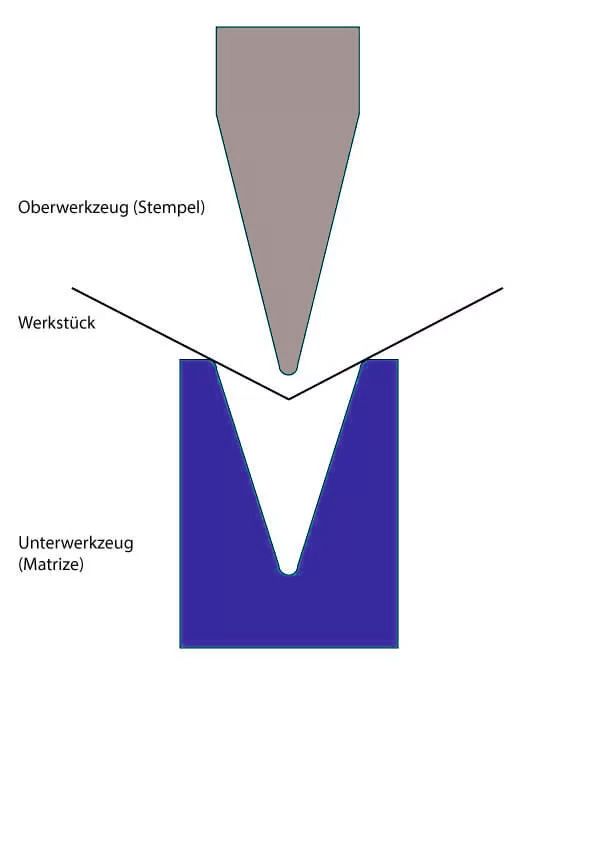
In free bending, the workpiece is pressed through the punch into the die without the die walls being completely touched by the workpiece. Pressing into the die causes the legs of the sheet metal to bend upwards, creating an angle. The size of the angle depends on the path; the deeper the workpiece is pressed into the die, the more acute the resulting angle. Modern machine control systems automatically determine the path and the associated pressing force, depending on the angle and the material properties (formability).
A wide variety of angles up to 179° can be produced with one set of tools by means of free bending. The process is therefore particularly cost-effective and flexible. Relatively low press forces and therefore relatively small and inexpensive machines are used. The biggest disadvantage of free bending was initially the inaccuracy of the angles produced. The sheet metal is not only plastically but also elastically deformed, whereby the elastic deformation disappears after the punch is lifted. As a result, the workpiece springs back and the size of the angle is reduced. Modern machines have a downstream sensor system that measures the angle after the first bending process and triggers re-bending if necessary. This has reduced the angular inaccuracies to around +/- 0.3°.
Embossing bending
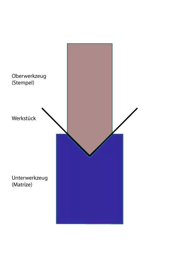
Embossing bending, on the other hand, involves a form fit, whereby the workpiece is pressed completely into the die so that no free space remains between the die, workpiece and punch. This means that the punch and die must fit together exactly, which means that a separate tool set is required for each angle. The moment the workpiece is fully pressed into the die, the punch cannot move any further. However, the press force is further increased by the machine control system until a specified value is reached. This stabilizes the angle, the springback is reduced to almost zero and the workpiece takes on the contours of the punch and die. The process is not path-dependent like free bending, but force-dependent. The pressing forces are three to eight times higher than with free bending.
The embossing bending process is mainly used to produce 90° angles in thin sheet metal parts where small bending radii are required. It is used particularly frequently in the mass production of electronic housings . It is also the preferred process when holes or openings are close to the bending edge. Beads, hinge rollers, gills and Z-edges are also produced by embossed bending.
Folding and closing
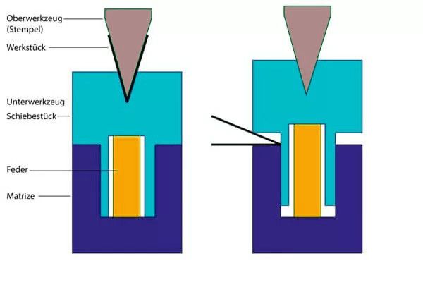
Sheet edges are often bent completely so that the bending legs are parallel to each other. This either stabilizes the finished part or creates edge protection. Folds are often used to hang another part on later. Folding and closing is carried out in two separate steps. First, an angle of 30° is pre-bent, then the angle is pressed closed. When folding, there is a gap between the bending legs, while they are pressed together completely when closing.
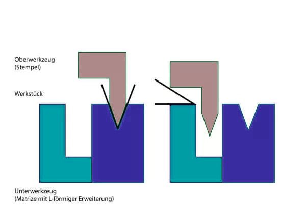
Special tools are required to carry out both steps on one machine. The easiest way to do this is to screw an L-shaped extension onto a standard die. The workpiece is first pre-bent in the die. The die holder then moves backwards, the punch moves deep into the L and closes the angle between the die support and a parallel surface on the punch. Another option is a special die in which the die for pre-bending lies in a spring-loaded sliding piece, which creates an opening on the side in the unloaded state. During pre-bending, the spring is first pressed downwards, the free space closes and the workpiece is bent freely. The workpiece is then pushed into the opening on the side. The punch is moved into the die as far as it will go, presses it down and thus closes the side opening, which closes the angle. This shortens the working time, as the die does not have to be moved and the punch travels shorter distances.
Calculations for bending
Bent sheet metal parts often contain a large number of edges, which is why it is very difficult to determine the sequence in which these are produced. The individual bending processes must not damage or destroy previously bent edges. The workpiece should rarely have to be rotated, turned or removed from the machine between bending operations. Modern programming systems help the operator with this, as the bending sequence is suggested, simulated and then optimized by the system.
During bending processes, the sheet metal is stretched at the outer edge, which lengthens the distance along the outer edge. The blank must therefore be shortened by the designer; this is referred to as a bending factor, for which there are standardized formulas. These formulas take into account the type of material, sheet thickness, inner radius and bending angle, but not the tools, machines and processes used. The actual bending factors can therefore only be determined by trial bending processes. The values determined are summarized in tables to facilitate the design of future sheet metal parts.
Press brakes
All of the above processes are carried out using so-called press brakes, which consist of the following components.
The machine frame, consisting of side parts and a cross beam made of solid steel, as well as the work table, forms a stable basic structure. Hydraulics and a drive for the press beam are required to generate and transfer the pressing pressure, which generates pressing forces of 50 to 3000 tons, allowing very thick sheets to be bent. The press beam is used to hold the tools that transfer the pressing pressure to the workpiece, the punches. The press table is used to hold the tools that serve as a mold, the dies with a die inside.
Die bending presses also contain a backgauge system with which the workpiece is positioned. Support brackets and bending aids are used to hold and guide the workpiece within the machine. A central control system regulates, monitors and synchronizes the individual machine functions and their interaction.
An operating station with monitor and modern software enables the work steps to be triggered and controlled from the outside. The operating station has input elements such as a keyboard and mouse, which the operator uses to tell the machine what to do. While the program is running, the operator can always view and monitor the current and subsequent work steps.
If you have any questions about sheet metal processing, please do not hesitate to contact us!